Sunday, November 25, 2012

Compound Interest Program


Important: Use Math.pow commend to find the power

Simple Averaging Program


Important: In this project first we have to add Scanner library to our project.

Monday, September 17, 2012

All About Connectors 1 : VGA Connector


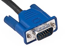
A Video Graphics Array (VGA) connector is a three-row 15-pin DE-15 connector. The 15-pin VGA connector is found on many video cards, computer monitors, and some high definition television sets. On laptop computers or other small devices, a mini-VGA port is sometimes used in place of the full-sized VGA connector. 

SVGA port.jpg

 The VGA interface is not engineered to be hot pluggable (so that the user can connect or disconnect the output device while the host is running), although in practice this can be done and usually does not cause damage to the hardware or other problems. However, nothing in the design ensures that the ground pins make a connection first and break last, so hot plugging may introduce surges in signal lines which may or may not be adequately protected against. Also, depending on the hardware and software, detecting a monitor being connected might not work properly in all cases.


Advantages of VGA over DVI

Function


DVI doesn't have to convert analog-to-digital or digital-to-analog. However, VGA has to convert digital to analog, which results in loss of the signal.

Identification


The DVI connector has pins that provide the same analog signals you'll find on a VGA connector. Therefore, you can connect a VGA monitor to it by using a plug adapter.

Benefits


With DVI, your display images will run seamlessly. With VGA, your images will suffer signal loss or corruption.

Considerations


You must have a video card that has the DVI port. Most new desktops will have this port.

Significance


DVI delivers digital data, meaning you'll have a clearer image. VGA won't give you this crisp image that you'll find with DVI.

Expert Insight


Lately, CRTs have greatly improved their analog signal processing technology to the point where there's no major difference between DVI and VGA. You'd have to be a professional photographer to notice the difference.


Saturday, September 15, 2012

Technology Coming Up 1 : Cars To Call For Help After Crashes


By 2015, the European Parliament wants all new cars to automatically alert emergency services in case of a crash, a service known as eCall. 


eCall: Time saved = lives saved

The introduction of eCall, technology designed to automatically call the European emergency number 112 when a car crashes, would enable rescue services to arrive faster, saving up to 2,500 lives a year and reducing the severity of injuries by 10 to 15 percent.

The eCall system is triggered by sensors in the vehicle like those which cause protective airbags to explode in a crash. Once triggered, the device automatically contacts the nearest emergency service centre, via the 112 service. It transmits the exact location of the vehicle and other data, such as the make of the car, and establishes a voice connection with the emergency services operator.

The eCall systems will also use satellites and mobile telephony caller location to determine the location of the crashed car. Based on the location, eCall will contact the nearest emergency center, and will also send a minimum set of data (MSD) that includes time, the direction in which the vehicle was travelling, vehicle identification, an indication if eCall was automatically or manually triggered and information about a possible service provider. Sending the extra data is likely to reduce misunderstanding and stress and helps to eliminate language barriers between the vehicle occupants and the operator, said the parliament.

The system must not be used to monitor a person’s movements or determine his or her location unless that person has been involved in an accident, the parliament said.

The full deployment of eCall requires cooperation between public authorities, car companies and mobile phone operators. If eCall becomes mandatory the car manufacturers will have to build it into every new car, and member states will have to upgrade their emergency call systems to comply with the eCall standards. 

Sunday, September 9, 2012

CCTV Camera Basics 1


Regardless of the technologies you use to design and implement a CCTV security system, there are a number of issues that must be addressed in all situations. First, what information do you want the system or component to provide? There are three possible answers: 

  • Detection – indicate something is happening in the field of interest

  • Recognition – determine exactly what is happening

  • Identification – determine who is involved in the activity 


But overall, all cameras are composed of three basic elements


  • Image sensor – converts light image to electronic signals
  •  Lens – gathers light reflected from a subject
  • Image processing circuitry – organizes, optimizes, and transmits signals


           CCTV cameras are available in monochrome, color, and day/night (combines color and monochrome).

Monochrome’s advantages are higher resolution, less light required, and generally lower cost. Color, on the other hand, offers better overall representation of a scene (with proper light), as well as improved capabilities for identification and prosecution. Day/night cameras offer the best of both worlds – and they are increasingly becoming the camera technology of choice for both outdoor and indoor applications.

Image Sensors


A charge-coupled device (CCD) is a device for the movement of electrical charge, usually from within the device to an area where the charge can be manipulated, for example conversion into a digital value.
The heart of the modern CCTV camera is the Charge Coupled Device (CCD) sensor. A CCD consists of a flat array of tiny, light-sensitive photodiodes that converts light into an electrical signal. Each diode produces a voltage that’s directly proportional to the amount of light falling on it. No light would produce zero voltage, and therefore, a black level. Maximum light would produce a maximum voltage (a white level). In between these extremes are shades of grey. In the case of a color camera, a chrominance signal is superimposed onto the luminance signal to carry the color information.

Video Signal

All video motion images are actually made up of still images — or frames. Each frame is composed of two fields. One field of video is created when the CCD is scanned across and down exactly 262 1/2 times – and this is reproduced on your monitor. A second scan of 262 1/2 lines is exactly one-half of a line down and interlaced with the first scan to form a picture with 525 lines. When these two fields are properly synchronized and interlaced in a 2:1 ratio, they form a complete still frame of video. CCTV cameras use AC voltage to synchronize this process of creating motion video. 
In countries like the US that use 60 Hz (cycles) alternating current, each second of video contains 60 fields, which forms 30 frames. In Europe and other regions using 50 cycles, there are 50 fields and 25 frames of video per second. To the human eye, these frames of video appear as moving images.


Optical Fiber Communication

Fiber-optic communications is based on the principle that light in a glass medium can carry more information over longer distances than electrical signals can carry in a copper or coaxial medium or radio frequencies through a wireless medium. The purity of today’s glass fiber, combined with improved system electronics, enables fiber to transmit digitized light signals hundreds of kilometers without amplification. With few transmission losses, low interference, and high bandwidth potential, optical fiber is an almost ideal transmission medium. 

What is Optical Fiber?


An optical fiber (or optical fibre) is a flexible, transparent fiber made of glass (silica) or plastic, slightly thicker than a human hair. It functions as a wave guide, or “light pipe” to transmit light between the two ends of the fiber.The field of applied science and engineering concerned with the design and application of optical fibers is known as fiber optics. 

In the 1920s, the same basic technology was used to actually transmit full images. In the 1930s that technology was used practically to illuminate the inside of a surgery, allowing for much more precise surgery. Optical fiber continues to be used in surgery, especially to facilitate less invasive internal surgeries. The first true optical fiber appeared in the 1950s, and by the end of the decade experiments were underway with a type of fiber very similar to that used today, with glass fibers coated with a transparent sheath 


How Fiber Works


The operation of an optical fiber is based on the principle of total internal reflection. Light reflects (bounces back) or refracts (alters its direction while penetrating a different medium), depending on the angle at which it strikes a surface.This principle is at the heart of how optical fiber works. Controlling the angle at which the light waves are transmitted makes it possible to control how efficiently they reach their destination. Lightwaves are guided through the core of the optical fiber in much the same way that radio frequency (RF) signals are guided through coaxial cable. The lightwaves are guided to the other end of the fiber by being reflected within the core.
  • Core: The center of the fiber where the light is transmitted. 
  • Cladding: The outside optical layer of the fiber that traps the light in the core and guides it along - even through curves. 


Multimode & Singlemode Fibers


Multimode & Singlemode fiber are the two types of fiber in common use. Both fibers are 125 microns in outside diameter - a micron is one one-millionth of a meter and 125 microns is 0.005 inches- a bit larger than the typical human hair. Multimode fiber has light traveling in the core in many rays, called modes. It has a bigger core (almost always 62.5 microns, but sometimes 50 microns ) and is used with LED sources at wavelengths of 850 and 1300 nm (see below!) for slower local area networks (LANs) and lasers at 850 and 1310 nm for networks running at gigabits per second or more. Singlemode fiber has a much smaller core, only about 9 microns, so that the light travels in only one ray. It is used for telephony and CATV with laser sources at 1300 and 1550 nm. Plastic Optical Fiber (POF) is large core ( about 1mm) fiber that can only be used for short, low speed networks. 

Step index multimode 
                                           was the first fiber design but is too slow for most uses, due to the dispersion caused by the different path lengths of the various modes. Step index fiber is rare - only POF uses a step index design today. Due to its large core, some of the light rays that make up the digital pulse may travel a direct route, whereas others zigzag as they bounce off the cladding. These alternate paths cause the different groups of light rays, referred to as modes, to arrive separately at the receiving point. The pulse, an aggregate of different modes, begins to spread out, losing its well-defined shape. The need to leave spacing between pulses to prevent overlapping limits the amount of information that can be sent. This type of fiber is best suited for transmission over short distances. 

Graded index multimode
                                                  fiber uses variations in the composition of the glass in the core to compensate for the different path lengths of the modes. It offers hundreds of times more bandwidth than step index fiber - up to about 2 gigahertz. Contains a core in which the refractive index diminishes gradually from the center axis out toward the cladding. The higher refractive index at the center makes the light rays moving down the axis advance more slowly than those near the cladding. Due to the graded index, light in the core curves helically rather than zigzag off the cladding, reducing its travel distance. The shortened path and the higher speed allow light at the periphery to arrive at a receiver at about the same time as the slow but straight rays in the core axis. The result: digital pulse suffers less dispersion. This type of fiber is best suited for local-area networks. 

Singlemode
                          fiber shrinks the core down so small that the light can only travel in one ray. This increases the bandwidth to almost infinity - but it's practically limited to about 100,000 gigahertz - that's still a lot! 

How do I know what type of fiber I need?

This is based on transmission distance to be covered as well as the overall budget allowed. If the distance is less than a couple of miles, multimode fiber will work well and transmission system costs (transmitter and receiver) will be in the $500 to $800 range. If the distance to be covered is more than 3-5 miles, single mode fiber is the choice. Transmission systems designed for use with this fiber will typically cost more than $1000 (due to the increased cost of the laser diode). 


Should I install single-mode or multimode fiber?

This depends on the application. Multimode fiber will allow transmission distances of up to about 10 miles and will allow the use of relatively inexpensive fiber optic transmitters and receivers. There will be bandwidth limitations of a few hundred MHz per Km of length. Consequently, a 10 mile link will be limited to about 10 to 30 MHz. For CCTV this will be fine but for high speed data transmission it may not be.
Single-mode fiber on the other hand will be useful for distances well in excess of 10 miles but will require the use of single-mode transmitters (which normally use solid-state laser diodes). The higher cost of these optical emitters mean that single-mode equipment can be anywhere from 2 to 4 times as expensive as multimode equipment.